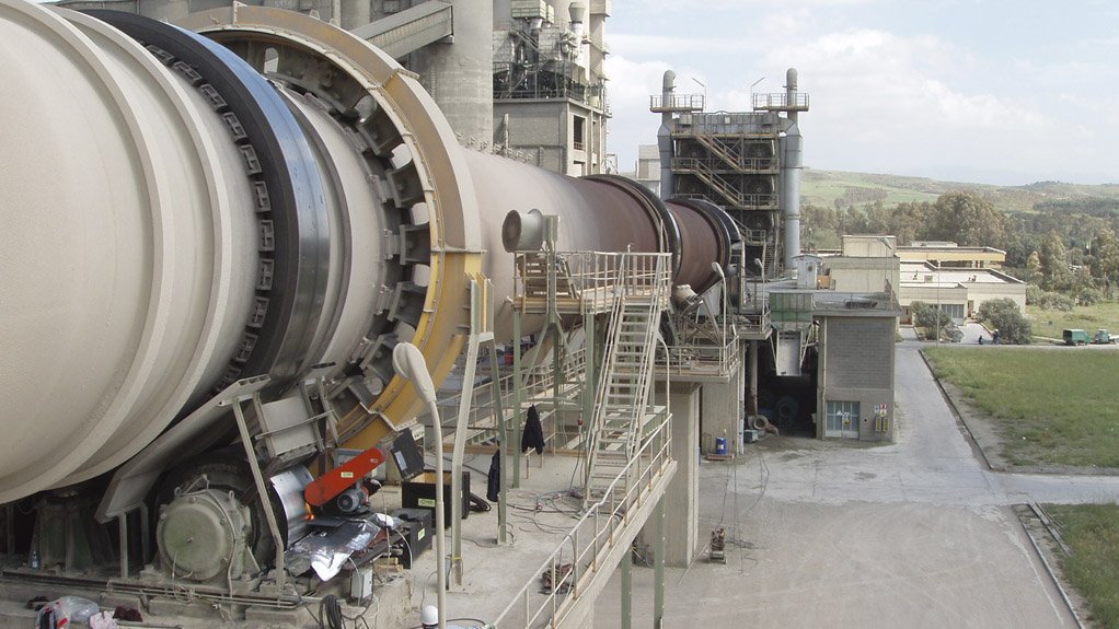
Furnace and industrial services provider Dickinson Group offers an on-line tyre and trunnion roller surface reconditioning service, which enables worn or damaged running tread faces of tyres and rollers to be machined while the vessel is in operation, thereby reducing downtime.
The company explains that tyre and trunnion rollers are the support and load bearing bases for the rotary kiln. The overall condition of the tyres and rollers adversely affects the kiln alignment, load distribution and kiln vibration amplitude. Therefore, any wear on the contact surfaces of the kiln tyres and support rollers renders it difficult to make proper support roller adjustments to achieve alignment.
The ideal hot kiln alignment procedure involves not only the horizontal and vertical axes of the shell, but also the balance of the axial thrust of the kiln. The company advises that when the tyres and support rollers are worn on the contact surfaces, the roller adjustment and kiln axial thrust balancing procedure becomes delicate. “In extreme cases, adjustments to rectify the kiln misalignment may become ineffective.”
Fortunately, the company notes that, excessive wear of tyres and support rollers can be eliminated during the process of resurfacing and grinding. The conventional reconditioning methods that involve removal of roller assembly units, workshop machining and reinstallation of the rollers tend to be expensive mainly because of the cost of the inherent downtime and consequential loss of production. Dickinson’s on-line tyre and trunnion roller surface reconditioning service alleviates the costs associated with the consequential loss of production.
Common Wear Problems
Concave and convex wear present the most common problems in kiln tyre and support roller wear. To control the kiln axial thrust, the roller shafts are skewed and this procedure has a direct effect on the mating surface profile of the support rollers and the tyre. The axis of the roller shaft is no longer parallel to the axis of the tyre. This means that the edges of the tyre on both sides of the tread face will have higher load concentrations than at the centre of the tyre.
When the rotary kiln operates in this condition for some time, the tyre will have accelerated wear on its edges, giving it a convex shape. The support rollers are wider than the tyre, hence, the surface of the rollers will develop concave wear. Since this is the desired adjustment position of the rollers to control the axial thrust of the kiln, this kiln design makes concave and convex wear inevitable.
Dickinson warns that problems beginning with tyres and trunnion rollers can quickly propagate throughout the rest of the rotary kiln. This can result in increased shell vibrations, excessive load on the drive mechanism, damage to rotary kiln inlet and outlet seals, premature refractory lining failure, cracked foundation pads, or increased wear and damage on the girth gear.
The company states that, the on-line reconditioning service results in optimum kiln mechanical stability, maximum production, and reduced maintenance and energy costs.
Tyre and Roller Grinding
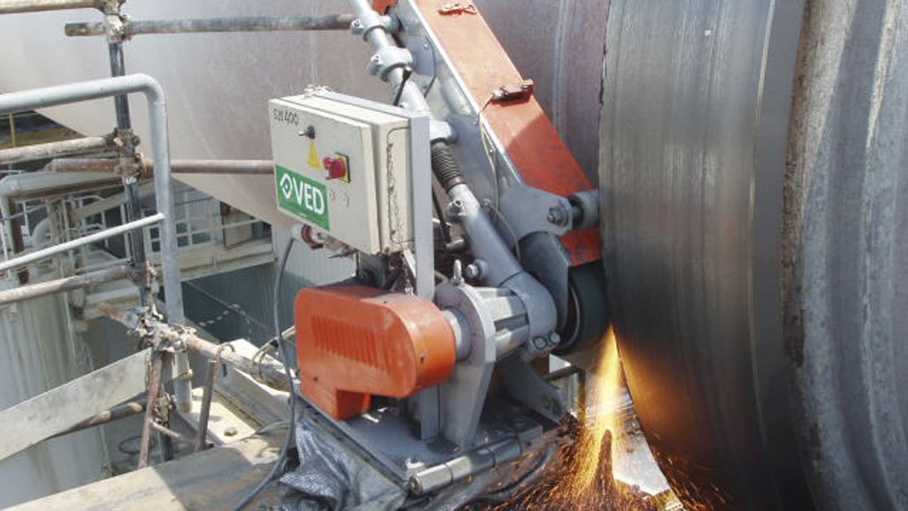
When the company conducts in situ grinding of tyres and support rollers, no kiln downtime is needed. The company’s internationally-trained grinding engineers constantly monitor axial thrust of the kiln and bearing temperature throughout the grinding process, carrying out roller adjustments where required to stabilise axial movement and temperature.
Dickinson uses high-quality portable belt grinding SM400 kiln tyre grinding machines and SMF 1000 kiln roller grinding machines, from Italian company Vetroresina Engineering Development.
The company explains that when machining a tyre, the machining rig is set to the vessel inclination and the ceramic tipped cutting tool is set at the horizontal tangent height of the tyre. Using guide rollers, the cutting head is forced to follow the tyre. This ‘floating’ arrangement ensures a flat finish regardless of tyre movement. A parallel surface of within 0.5 mm on the diameter is generally achievable with this method. Tool feed rate is controlled by a variable speed drive that can be adjusted to the desired surface finish.
For the trunnion rollers, the machining rig is mounted directly onto the bedplate. Should this not be possible, the machining rig can be mounted onto a temporary structure welded to the bedplate. The machining rig is set parallel to the trunnion roller centreline and the cutting tool is set at the horizontal tangent height of the trunnion roller. A parallel surface of within 0.2 mm on the diameter can be achieved in this way.
During the machining process, the vessel axial thrust characteristics will change. The machining crew monitor vessel reactions and make compensatory adjustments to trunnions to maintain equilibrium of the vessel.
After completion of the machining process, the finished diameter of the tyre or trunnion roller is measured using an electronic diameter-measuring device and trunnion roller settings are calculated to compensate for the reduced diameters. The vessel is left in a balanced state of axial thrust, although it is a normal procedure for the vessel to require further tuning adjustments. These adjustments are normally carried out eight to ten days after completion of the machining process.
Edited by: Zandile Mavuso
Creamer Media Senior Deputy Editor: Features
EMAIL THIS ARTICLE SAVE THIS ARTICLE
To subscribe email subscriptions@creamermedia.co.za or click here
To advertise email advertising@creamermedia.co.za or click here


